CIVILSTRICT Engineering Consultant
Core services

Services

Two core groundwater specialisms, supported by six related areas across water facilities, irrigation, agriculture, flood protection, electromechanical works and construction management.
Service A

Hydrogeological studies & deep wellfield design

  • Regional and site-scale aquifer investigations
  • Deep well design and drilling supervision to depths of 800 m
  • Step-drawdown, constant-rate and recovery pumping tests
  • Well rehabilitation addressing fouling, silting and declining yield
  • Water chemistry and vertical and lateral salinity profiling
  • Artificial recharge and sustainable abstraction modeling
MODFLOWFEFLOWPHREEQCMIKE SHEAquiferTest
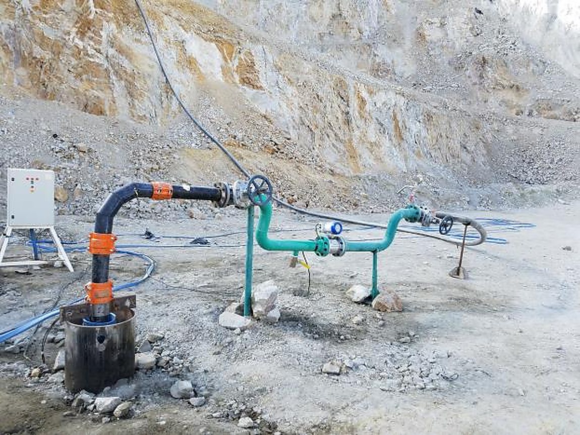
Wellhead assembly during a constant-rate pumping test
Production wellhead during a constant-rate pumping test
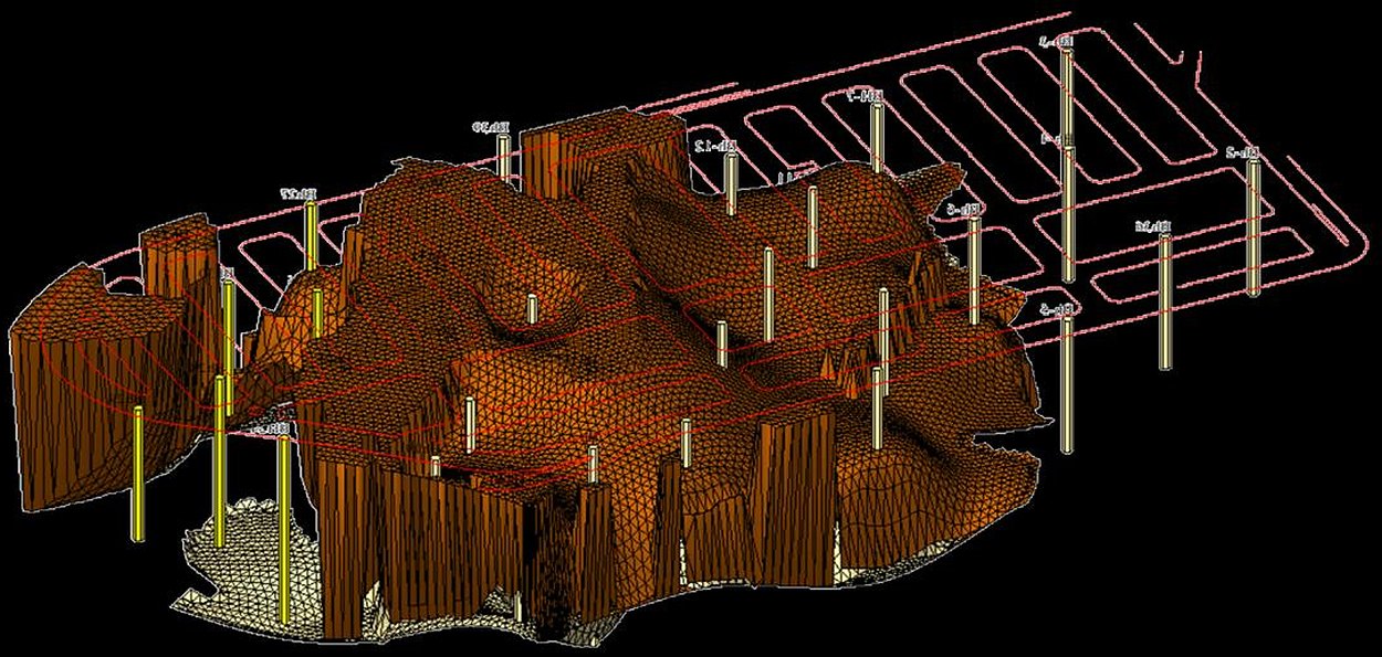
3D dewatering model with drainage network
3D dewatering model with its drainage network
Service B

Permanent and temporary groundwater control

  • Permanent and temporary dewatering for construction sites and existing assets
  • Mounding and uplift pressure mitigation beneath deep basements
  • Drainage systems: sump pits, interceptor drains and sub-drains
  • Seepage and infiltration modeling under urban and coastal infrastructure
  • Geophysics integration for subsurface mapping and risk identification
MODFLOWSEAWATHYDRUSVADOSE/WSEEP/WERT / EM
Related areas

Work delivered alongside the studies, or on its own

Water & treatment facilities

  • Pumping station design, pump selection and operating curves
  • Reverse osmosis desalination plants and their ancillaries
  • Treated effluent reuse systems
  • Transmission mains and storage tanks

Irrigation & land reclamation

  • Land reclamation and agricultural area planning
  • Modern irrigation network design and water demand calculation
  • Irrigation stations with filtration and fertigation systems
  • Irrigation mains and in-field distribution networks

Flood protection & stormwater

  • Flood risk mapping and wadi course identification
  • Surface runoff modeling and design discharge calculation
  • Design of protection structures and drainage works

Electromechanical works

  • Pump and motor selection with power calculations
  • Control panels and electrical supply for stations
  • Lighting works for roads and facilities
  • Measurement, monitoring and automatic control systems

Agricultural consultancy

  • Soil and water suitability assessment for cultivation
  • Crop selection and cultivation cycle planning
  • Fertilisation and crop treatment programmes
  • Nurseries, propagation greenhouses and production programmes

Project management & supervision

  • Engineering supervision of drilling, installation and site works
  • Review of shop drawings and contractor submittals
  • Tender documents and bid evaluation
  • Programme monitoring and review of payment applications
  • Commissioning tests and post-commissioning performance records
Delivery method

Delivery stages

Each stage's output is the next stage's input, and the scope of each stage varies with project size and site conditions.

01

Investigation & survey

Geophysical surveys, review of existing data and drawings, and a survey of current site conditions.

02

Field testing

Pumping tests, level measurements, and soil and water analyses as the project requires.

03

Modeling & calibration

A numerical or analytical model built and calibrated against measured data, then run through operating and risk scenarios.

04

Detailed design

Detailed design of the facility or system, execution specifications and tender documents.

05

Supervision & handover

Supervision of construction and installation, commissioning tests, and documented post-commissioning performance.
Technical outputs

Examples of technical outputs

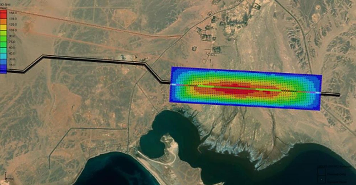
Resistivity section overlaid on satellite imagery
Resistivity sections over satellite imagery
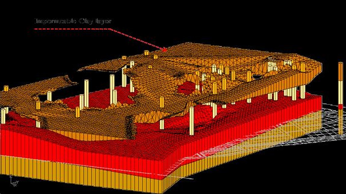
3D model of subsurface layers
3D subsurface layer models
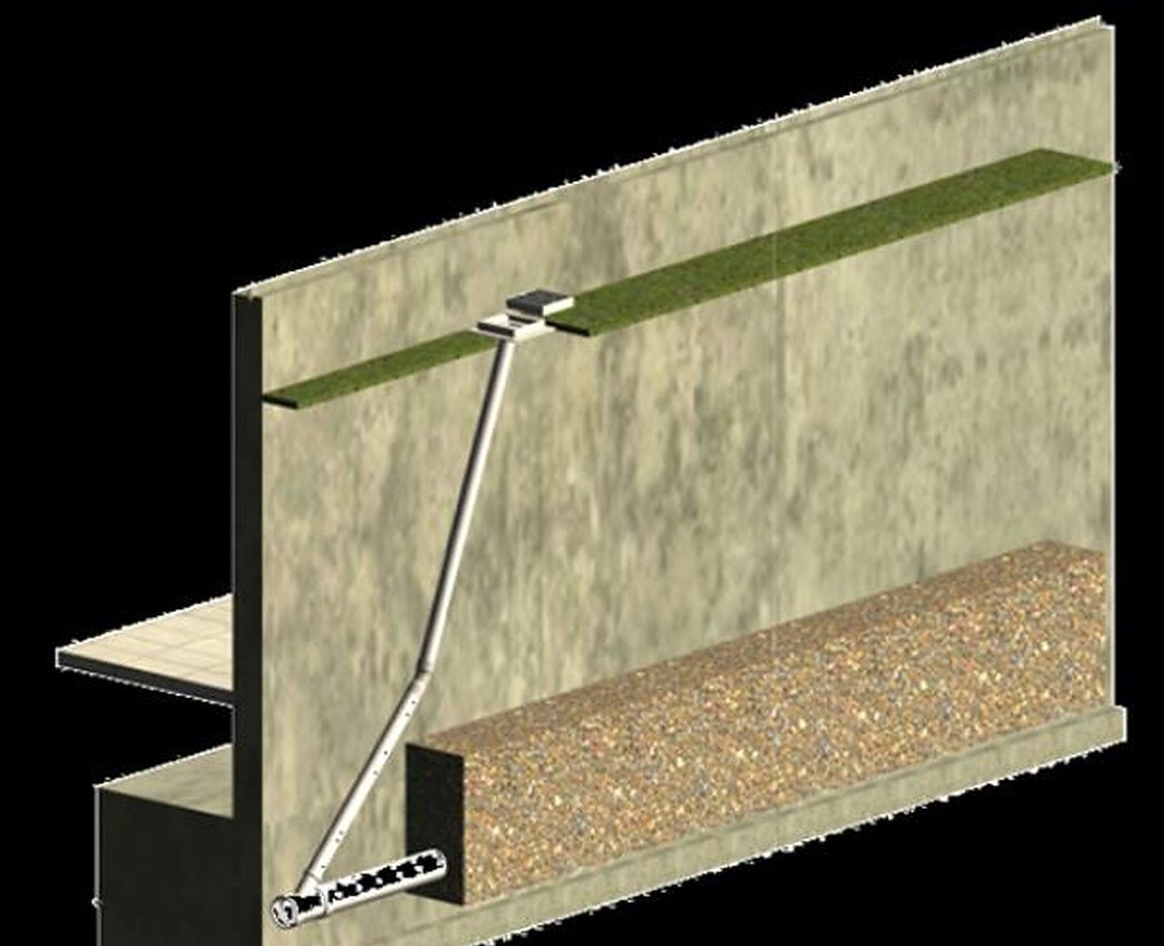
Subsurface drain behind a retaining wall
Drainage details behind retaining walls
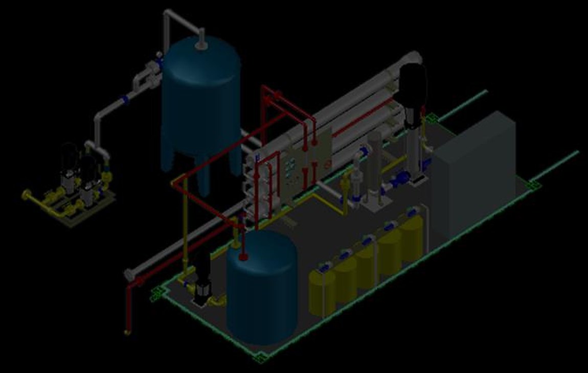
Isometric layout of a pumping station
Isometric layouts for pumping and treatment plants
Construction details

Perforated drain in a gravel trench

A typical detail for subsurface drainage systems; dimensions and fill materials change with the model results and the required discharge.

F.G.L. 0.00 Natural pervious fill Non-woven geotextile Rapid drainage material Perforated uPVC pipe Ø200 Max. depth 1.00 m Width 500 mm
Typical construction detail: a perforated pipe bedded in rapid drainage material wrapped in non-woven geotextile, topped with natural pervious fill that protects the layer from clogging.

For technical enquiries or to discuss a project

Contact details